

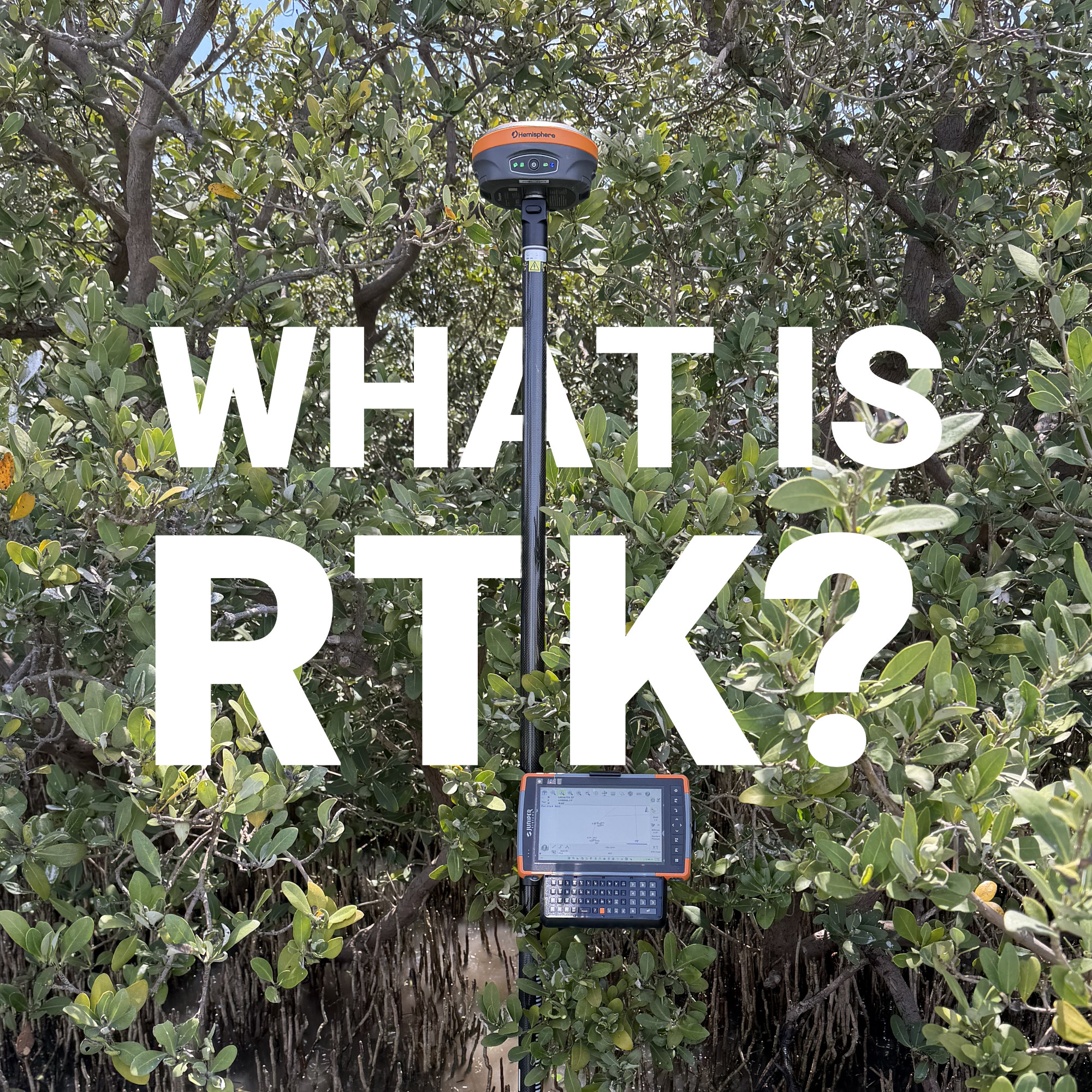
A rover holding a fix under open sky, then dropping to float the moment it passes under a stand of spruce, isn’t malfunctioning. It’s exposing the physical limit of carrier-phase positioning under obstructed sky views. That distinction, between what standalone GNSS can resolve and what RTK corrects for, is the entire reason the technique exists.
Real-Time Kinematic positioning takes a raw satellite fix accurate to a few metres and resolves it to one or two centimetres, on-site, in the time it takes to plant a pole. For surveyors, civil engineers, and construction crews across Canada, that’s no longer a specialized capability. It’s the accuracy floor the rest of the workflow is built on.
What Is RTK?
How RTK Resolves a Position
RTK Survey Applications in the Field
Sourcing Corrections: Base Station vs. Network RTK
Conditions That Determine Fix Quality
RTK Against Conventional Survey Methods
Matching Equipment to the Work
RTK Set the New Accuracy Standard
RTK is a differential GNSS technique that resolves carrier-phase ambiguities in real time to deliver centimetre-level positioning in the field, rather than after post-processing.
A standalone GNSS receiver derives position from pseudorange measurements alone, which places a point within a few metres of true location. That’s adequate for consumer navigation. It’s not adequate for a legal boundary corner, a pipe invert, or a design grade stake, where tolerances are measured in millimetres, not metres. RTK narrows that gap by comparing carrier-phase observations at a fixed, known-coordinate location against observations from a moving receiver, then transmitting the resulting correction stream to the rover as it collects.
The distinction from earlier differential methods is timing. Static and PPK (Post-Processing Kinematic) workflows record raw observations and resolve them later, often back at the office. RTK resolves the same ambiguities on the fly, so a crew knows the integrity of a shot before they’ve walked to the next point.
Modern RTK receivers track multiple GNSS constellations concurrently, GPS, GLONASS, Galileo, and BeiDou, rather than relying on GPS alone. That redundancy matters most in obstructed environments, where partial sky blockage from canopy or structures still leaves enough satellites in view to maintain a fixed solution.
An RTK system has two functional components: a reference station (base) and a mobile receiver (rover).
The base occupies a static, known-coordinate point and continuously logs carrier-phase and code observations from the same satellite constellation the rover is tracking. Because its true position is known, any discrepancy between the observed and expected signal, atmospheric delay, satellite clock error, orbital error, gets isolated and packaged as a correction.
The rover applies that correction to its own simultaneous observations, cancelling out the errors common to both receivers. Once enough satellites are resolved with sufficient geometry, the receiver reaches an integer-fixed solution, the state that delivers centimetre accuracy rather than the sub-metre “float” solution that precedes it.
Corrections reach the rover almost universally via NTRIP (Networked Transport of RTCM via Internet Protocol) over cellular data, which is the standard most RTK GPS and GNSS receivers are built around. Time to fix, and the stability of that fix once achieved, depends on baseline length, satellite geometry, and signal obstruction as much as on the receiver itself.
An RTK survey is any survey conducted using this base-and-rover architecture in place of, or alongside, a conventional total station.
That covers most of the day-to-day work on a modern crew’s plate:
Data collection software such as FieldGenius sits on top of the receiver, displaying live coordinates against design files and logging observations without manual note-taking. The receiver resolves position; the software manages the workflow around it.
A crew doesn’t necessarily need to deploy its own base station on every job. Three approaches are in common use:
Most production crews default to network corrections for routine work and keep base-and-rover capability in reserve for sites outside network coverage or projects that require a controlled local datum tie.
RTK accuracy is not a fixed number. It’s a function of site conditions the receiver can’t fully compensate for:
A crew getting inconsistent fixes on a site that should support clean RTK work is usually running into one of these variables rather than a hardware fault. That’s the most common diagnostic conversation Bench-Mark has with field crews: the receiver is performing as designed, and the constraint is antenna setup or line of sight.
Conventional instrument survey, theodolite and level work, resolves each point through sequential manual measurement and calculation. Every step in that chain is a point where error can enter, and every point takes real time to occupy and reduce.
RTK collapses that sequence into a single occupation. A rover held over a point returns a resolved coordinate in seconds, with error-checking embedded in the fix itself rather than applied afterward. The practical result is a survey that once required a full crew and a full day often gets completed by one or two people before lunch, with point-to-point consistency that manual reduction rarely matches.
Not every GNSS receiver on the market is built to survey tolerances. The difference between a consumer-grade unit and a proper survey receiver, such as the Hemisphere S631, comes down to antenna phase center stability, multi-frequency tracking, and how the firmware manages PCO/PCV corrections in real time. Bench-Mark supports both established survey-grade platforms and lower-cost alternatives like the GeoMeasure Nano 7, for crews weighing budget constraints against the precision a given job actually requires.
RTK didn’t just accelerate fieldwork. It reset what “accurate enough” means across an entire discipline. Centimetre-level positioning resolved in real time, rather than reconstructed after a day of post-processing, is now the tolerance construction schedules, boundary retracement, and engineering design are built around.
Meeting that standard consistently comes down to matching the right receiver, antenna, and correction source to the site in front of you, not troubleshooting it after a stakeout comes back wrong.
