
Global Positioning System (GPS) technology has revolutionized the way we navigate and gather location data in various applications, from agriculture and construction to surveying and geodesy. Among the advanced techniques within GPS, Real-Time Kinematic (RTK) and Static Measurements stand out as two prominent methods for achieving high-precision positioning accuracy. Both use the corrections from Global Navigation Satellite System (GNSS) to produce an exact location with precise coordinates. However, the technique used to generate precise coordinates are different, and have different considerations that must be considered. All modern GNSS receivers are capable of these two operating modes and a deeper understanding of the differences between RTK and Static GPS will help you get the most out of your equipment in the field.
Principles of GNSS Measurements
Before getting into the precise in and outs of how a static measurement and RTK measurements work, it is useful to understand how GNSS receivers actually obtain a positions with accurate coordinates. GNSS satellites broadcast several different pieces or information that are used by a GNSS receiver on the ground.
Ephemeris Data
This information includes precise orbital parameters of an individual satellite, including current position, velocity, and acceleration in space. This information is used by a receiver to help predict the future position of the satellite.
Clock Correction Parameters
GNSS satellites contain an onboard atomic clock, and although highly accurate, there are still minor errors due to a host of factors. The navigation message provides clock correction parameters to help the receiver synchronize its internal clock with the satellite’s clock. This helps improve the accuracy of distance measurements.
Almanac Data
The almanac provides approximate orbital information for all satellites in a constellation. This aids in helping the receiver lock onto and identify visible satellites when initially turned on, or after signal interruptions.
Modulation and Coding Parameters
Information about how the navigation message is modulated and encoded is provided so that the receiver can properly demodulate and decode signals to extract data.
This information is information is carried on two different waves from from the satellite to the receiver. These are the carrier wave and navigation message. The carrier wave is a high-frequency electromagnetic signal that carries no navigation information, but provides the precise timing information. By measuring the phase shift of the carrier wave between the satellite and the receiver, the receiver can measure the relative distance to the satellite with high precision. The navigation message contains much of the information already discussed above. (As a side note, you can read about how these signals are affected by ground based interference by checking out the effect of 5G on satellite signals in this article: National Spectrum Policy: Interference Issues in the 5G Context.)
The final thing that must be considered is the integer ambiguity. The integer ambiguity is related to the whole number of wavelengths between the satellite and receiver. While the carrier-phase measurement provides information on the wavelength, it doesn’t directly give the number of wavelengths. This integer part is known as the integer ambiguity. Resolving this ambiguity, helps determine how many full wavelengths fit into the measured carrier phase. Once resolved, the carrier phase measurement can be correctly converted to geometric distances.
How Does a Receiver Determine an Exact Location
When calculating a new point with a GNSS receiver, first collects signals from multiple satellites in the sky. A minimum of 5 satellites from a single constellation must be used in determining the initial position. The receiver then determines the distance between itself and each satellite. Using this determined distance, GNSS receivers can then use trilateration to calculate a position. This trilateration equation takes into account a number of factors including atmospheric parameters, and potential multi-path issues. A latitude, longitude and elevation are then produced, which is then often transformed into another coordinate system.
Before getting into the precise ins and outs of how a static measurements and RTK measurements work, let us first take a look at how each method works on a more basic level. You may end up with nearly identical coordinates at the end of the survey, but both produce this calculated position through very different methods.
RTK (Real-Time Kinematic)
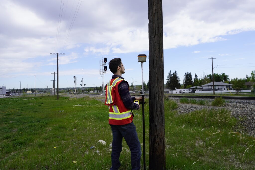
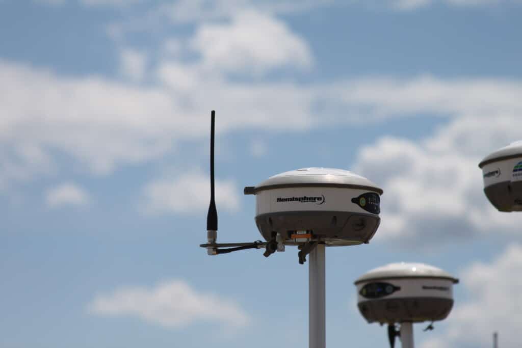
RTK is a high-precision GNSS technique that enhances the accuracy of positioning in real-time. A typical setup consists of two gps receivers, either in the form of the base and the rover, or of a rover and a fixed reference station. Traditionally, the solution was performed with an RTK GPS solution, where only GPS satellites were used. However, with the advent of 7th generation RTK technology (receivers like the Hemisphere S631 and Trimble R12i), multi-constellation RTK solutions can be calculated.
In an RTK solution a base station is relied upon to provide correction signals to the rover. Correction signals can be sent over a variety of different methods, but the most common are via UHF radio and cellular networks. These correction signals compensate for errors caused by atmospheric conditions and satellite clock inaccuracies, enabling centimetre-level accuracy in real-time. This means that observation times on a single position can be as short as one second, and calculating on a moving rover.
This technique provides relative positioning, in other words the rover is accurate in relation to the base. RTK accuracy is typically in the range of 8 mm in the horizontal and 15 mm in the vertical. In the Limiting Factorsand Accuracysection, we will cover some of the sources of error and considerations that will have to be considered. This technique is used on a day to day basis in many land surveying operations.
Static Measurements
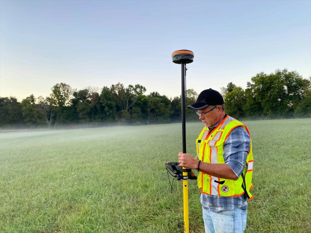
Static Measurements, on the other hand, involves collecting raw data over an extended period at stationary locations. A stationary receiver observes satellite information over a set time frame while in static mode. This collected raw data is then processed into a universal RINEX language. Typically, setups consist of a single receiver on a tripod, if one of the free government services are used for processing.
Once processed, the observation file is uploaded to a specialized post-processing software package that is used to calculate a better-quality position. This specialized software is often free, with services with CSRS-PPP and NOAA’s OPUS service (this article covers the differences between the two: CSRS-PPP vs OPUS: What is Better for Static Data Processing). Some of the tradeoffs of these software packages will be discussed in the next section.
Accuracy is dependent on a number of different factors, such as the recording interval, observation time, atmospheric conditions and receiver capabilities. Static observations aim to achieve the highest level of accuracy by mitigating factors like multi-path interference and atmospheric disturbances. Like RTK static measuring will generate centimeter level accuracy. This technique is used much more frequently in government surveys or in the establishment of known points in areas where no other known coordinates exist.
RTK (Real-Time Kinematic)
There are several limiting factors that must be considered when looking to take RTK measurements. First and foremost, RTK measurements provide a relative position that is accurate in relation to the base station. This position information, will have an offset to the real-world, unless a “correction factor” or localization is used to correct for this offset. This localization can typically be done one of two ways. Either a known point can be used to set the base over, or a known point can be located with the rover, with the adjustment made with the rover using software. When using a base and rover setup, this has to be done manually by the operator, but is often already completed on a network or VRS setup with no user input required. Alternatively, you can put the base in both RTK and static mode. This allows you to gain the advantage of both types of methods and to apply the correction factor after you have completed the survey.
One of the other limiting factors of an RTK method has to do with the base position, and the quality of the signals the base transmits. There are a host of different factors that can influence the base signal, including atmospheric conditions, terrain, and broadcast method. During an RTK measurement, the rover can only use the information from satellites that both the base and rover see. Without the base corrections, the higher degree of accuracy cannot be obtained. What this means is that you are limited by the baseline distance between the base and the rover.
Static Measurements
The most obvious disadvantage of static measurements is in the occupation time required to achieve acceptable positioning accuracy. In order to achieve the required accuracy a receiver in static mode is required to occupy the same point for several hours. (In fact you can get an idea of the time required in this video: 11. Are You Recording Static Properly? | Bench Mark). Unlike with the base and the rover setup, you cannot have a moving rover, you must stay stationary for the allotted time. Over the entirety of this observation time, the receiver in most cases cannot be adjusted or touched, as this will compromise the observation file.
Additionally, there are the limitations in the post-processing software. In the two above mentioned services, CSRS-PPP and OPUS are GPS and GLONASS only. This means they do not take advantage of all available global navigation satellite system options. In order to be able to use all the constellations that are already available in the raw data, additional software is required. Unfortunately, as the government agencies that run PPP and OPUS provide their own base station data, you will need a second receiver to collect raw data.
RTK (Real-Time Kinematic)
As briefly mentioned above, the main advantage of RTK systems is the ability to measure in real time a position. You can achieve accurate and repeatable positions in as little as 1 second with the rover. This allows for an RTK system to replace a total station in surveying jobs. Plus, with RTK, you do not have any of the drawbacks of a total station. You are not limited by line of sight, it is less dependant on operator skill, and a significantly longer baseline can be achieved. With an RTK systems you can achieve a baseline over 10 km, 25 km and 50 km depending on the method the base transmits by.
An RTK system can drastically increase the speed of a survey, especially when compared to a total station. As long as base corrections can be received, an accurate position can be established.
Static Measurements
The biggest advantage of a static measurement with GNSS receivers is that it allows you to establish control and a precise real world position, where one did not previously exist before. This can be used to correct the relative positioning that is obtained by an RTK system. This makes it an ideal method to be employed in remote areas or areas where survey control is missing or non-existent. In short, static measurements allow for the establishment of known coordinates, that can be used as highly accurate control points in RTK surveys.
Further, with a static measurement, you do not have to take into consideration any baseline or radio considerations. Only a single independently functioning receiver is working over a single point. This makes the setup simple especially when compared to a RTK survey.
RTK (Real-Time Kinematic)
RTK offers real-time accuracy at the centimeter level, making it ideal for applications that require immediate and precise positioning information. Applications such as topographic surveys, utility work, layout, cadastral, boundary work, water elevations and more can all benefit from RTK surveying methods. When properly configured with software, GNSS receivers can achieve significantly higher productivity especially when compared to total stations or older RTK GPS receivers.
However, the accuracy can be influenced by the distance between the base station and rover, atmospheric conditions, receiver capability and line-of-sight obstructions. RTK receivers are also precise, with an accurate relative position to one another. Unless a localization, or known position is used, the coordinates will not be accurate to the real world, unless otherwise corrected, as previously mentioned.
A good rule of thumb for RTK accuracy is 8 mm ± 1 ppm in the horizontal and 15 mm ± 1 ppm in the vertical, or +1 mm for every kilometre from the base station. This rule applied more generally to older GPS receivers, and is less rigid for newer 7th generation RTK receivers. For more information on how your baseline can affect your accuracy check out this video: 10. Hemisphere S631: Internet RTK with StormCaster.
Static Measurements
Static provides the highest accuracy achievable in GPS positioning, often surpassing the centimeter level. By collecting an observation over a longer period, the technique minimizes errors caused by various factors, resulting in incredibly accurate coordinates if the observation window is long enough. The trade-off is that the post-processing step can be time-consuming, and if anything happens to the receiver all data can be lost. A Static observation is often used to create control monuments, and help adjust RTK data into the real world.
Manufacturers typically report static data at 2.5 mm ± 1 ppm in the horizontal and 5 mm ± 1 ppm in the vertical. In order to achieve this accuracy long observation times must be undertaken, in the order of over 10 hours.
RTK (Real-Time Kinematic)
RTK requires a base station and a rover receiver. The base station accurately determines its own position and sends correction data to the rover in real-time. This base station may be owned by the operator and under their control, or owned by a network provider.
Both the base and the rover must have clear visibility the same satellites in order for a RTK accuracy to be obtained. Setting up an RTK system involves establishing a communication link between the base and rover, configuring the correct coordinate system, and performing a site calibration on known coordinates. At the end of the day, a good rule of thumb is; whatever the base and rover can both see, can be used in the RTK equation.
Depending on the RTK setup, several other additional pieces of equipment may be required. This includes external base radio systems (extend communication range), data collectors, tripods, poles, batteries and more. This can make an RTK setup quite cumbersome especially when compared to a static survey setup.
Static Measurements
The equipment setup for static involves placing a receiver at a stationary point for an extended period. This method requires at least one receiver, a tripod and a tribrach. Typically a survey marker is placed over which the base receiver is placed. Using the tribrach the instrument can be placed over the survey marker and levelled to ensure that you obtain repeatable and accurate position information.
This technique demands careful site selection to minimize multipath interference and maximize satellite visibility. Post-processing software, capable of handling long observation sessions, is used to compute accurate coordinates. Often times, free government services are available, like NOAA’s OPUS and NRCAN’s PPP-CSRS.
A static mode survey is often the easier to setup and reduces the number of possible user errors but may require more technical knowledge during the post processing phase.
RTK (Real-Time Kinematic)
The operational range of an RTK system is limited by the distance between the base station and the rover. As this distance increases, accuracy can decrease as error is propagated. Typically, UHF radios, like those found on the Hemisphere S631 can send signals out to 10 km (6.2 miles). Extended range can be found by using NTRIP solutions like StormCaster, or external radios 35 W radios that can extend range to over 32 km (20 miles). Check out this video on internal radio range on the Hemisphere S631 to get an idea: 5. Hemisphere S631: Radio Range.
The other option is to use a VRS network. With a VRS network, as long as there is base station and cell coverage you can achieve an RTK solution. In a VRS network, software is used to generate a virtual reference station over a calculated point. It achieves this by using a dense network of base stations on known coordinates (often surveyed in using static measurements). As long as you are in network coverage you can achieve an RTK solution. You can learn what kind of RTK setup is best for you in this article: What is the best RTK setup for me?
Static Measurements
Static has a broader operational range compared to RTK. Since the focus is on post-processing collected data, the technique is not constrained by real-time communication between base and rover. Single receivers can be used with no need for any external communication equipment. Wherever a tripod can be safely setup, or a receiver can be mounted to a level and stable surface, static observations can be taken.
The only time range must be taken into consideration for static measurements is during PPK measurements. You are constrained by baseline distances, and relative positioning accuracy will come into play.
RTK (Real-Time Kinematic)
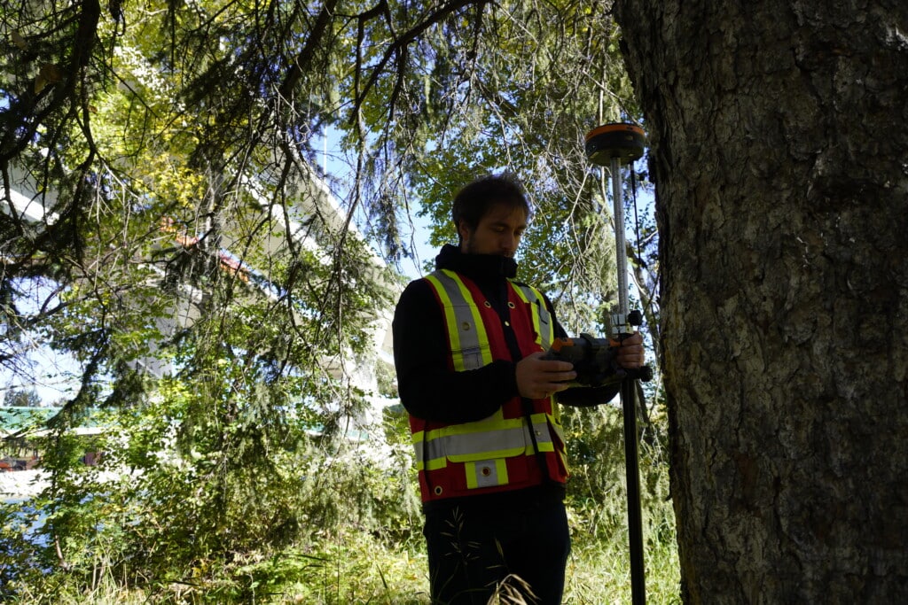
Real-time corrections in RTK are susceptible to atmospheric disturbances, ionospheric delays, and satellite clock errors. Tall buildings, trees, and other obstacles can lead to signal blockages and reflections, affecting accuracy and performance. As these signals are reflected and blocked, the roving receiver must filter out bad signals. This is where the real difference in performance comes between receivers like the Trimble R12i, Hemisphere S631 and Leica GS18 come from. Check out our playlist where we put these receivers to the test in different canopy environments: Hemisphere S631 Real World Tests.
When performing the survey, you have to take into account these factors when setting up the base position and when attempting to take an RTK measurement. The difference in RTK engine and technology with quickly come apparent when in these difficult environments.
However, you can do several things to help mitigate those factors to give yourself the best chance to shoot your points. First, ensure your base station is in the best possible position. Imagine yourself as the base station and when you are standing where it is placed. You want to be able to see as much of the sky as you can, with as few obstacles in the way as possible. This will allow the base station to broadcast as many corrections to the rover as possible, giving you the best RTK performance and higher accuracy. At the rover you want to ensure that you give enough time for the RTK equation to resolve and ensure that you are minimizing things that could affect the satellite and base signal.
Static Measurements
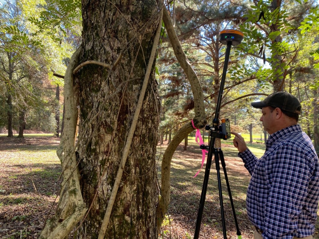
By collecting data over time, static minimizes the impact of atmospheric conditions and satellite geometry changes. This makes it less affected by short-term disturbances, resulting in higher accuracy, if long enough recording intervals are used. However, a static survey is still affected by all the factors mentioned above.
If you are going to be in an environment with lots of trees, building or obstacles, it is a good idea to make your observation window longer. That will help reduce the noise and thus error that will be created from these multi-path obstacles. Your receiver will only ever be able to use the satellite corrections from the sky that it can see. If you keep that in mind, you will achieve the best possible positioning accuracy.
RTK (Real-Time Kinematic)
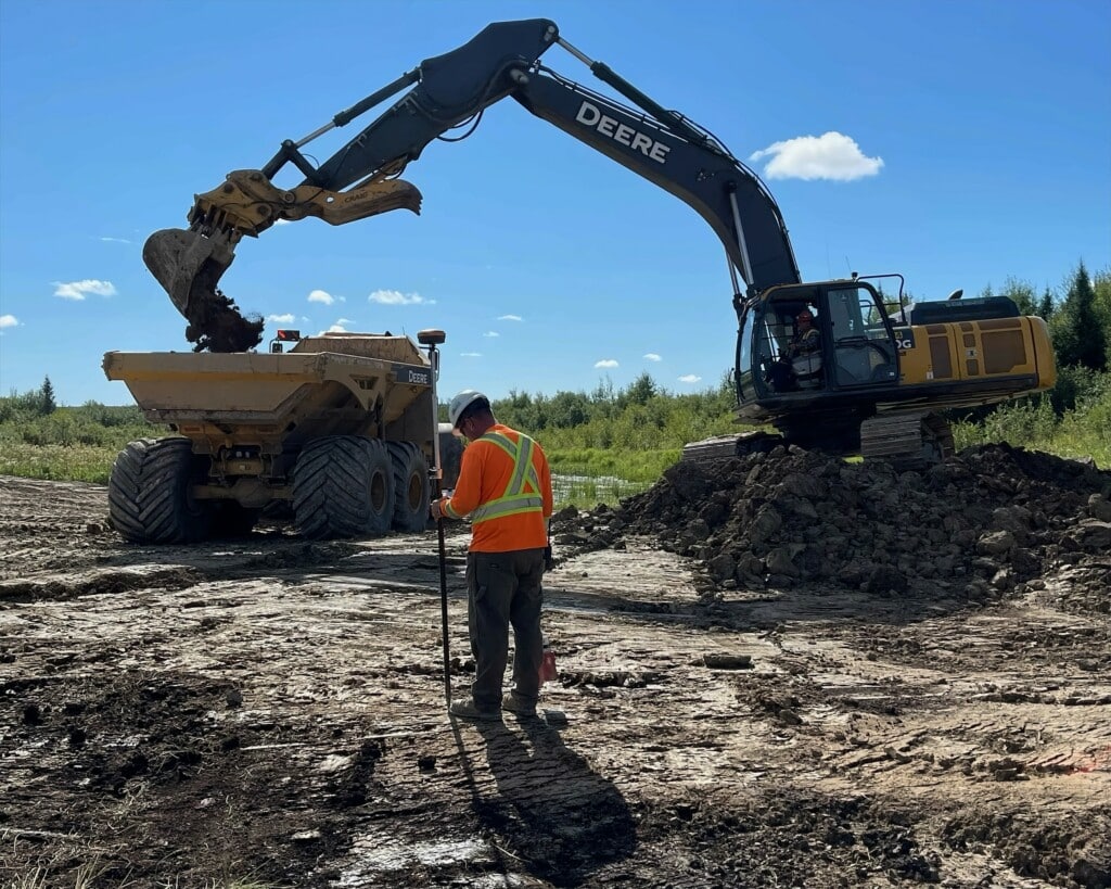
RTK is well-suited for applications that require instant, high-precision positioning, such as land surveying, construction layout, and precision agriculture. It enables immediate decision-making based on accurate real-time data. You can get live, cut and fill information, volume calculations, locate positions and more.
With a known point, you can correct your positioning accuracy into the real world. However, you can also perform the survey and obtain a relative position. With the an RTK receiver, you can use the relative positioning to perform monitoring. This is especially useful in operations like calculating volumes or determining the change in grade of an object applying corrections in the field. Alternatively, you can accurately determine the positioning of building corners, lot corners, or stake to lost survey monuments.
Static Measurements
Static finds its niche in applications where ultimate accuracy is paramount and real-time data isn’t critical. Geodetic surveying, deformation monitoring, and establishing precise control networks benefit from the meticulous accuracy offered by measuring positions with a static survey.
For those where absolute positioning is required, and as little error is possible is paramount the static survey is the method for you. The position you obtain will be able to apply corrections to RTK data, and allow you to obtain precise coordinates.
Can They Be Combined?
Up until this point, we have almost made it sound that each method is wholly independent of one another, with little cross over. However that is not the case, despite the difference between the two methods, they are often used in conjugation. What a surveyor can due is perform an RTK survey, and while performing the survey, collect static data. The raw static data can then be processed, with the position used to apply corrections to the collected RTK data. Alternatively, a previously collected static point can be used as a control monument that can be occupied by other the rover or base.
RTK (Real-Time Kinematic)
RTK provides instant positioning results, making it suitable for scenarios that demand rapid data collection. With observation times as short as 1s. However, the short observation time for each point can result in lower accuracy compared to static GPS. Data is generally collected using a handheld data collector and specialized software.
The specialized software is used to obtain and collect a point occupied by the rover. Once the point is occupied the operator use the hand held computer to obtain the point, and associate any information required for the survey. There are several different options for software, but popular options include MicroSurvey’s FieldGenius, Trimble’s Access and Carlson SurvCE.
Within this software you can make calculations in the field, get real time positioning coordinates, information on your receiver, find and locate points and more.
Static Measurements
As the name suggests, static involves longer data collection periods, often ranging from hours to days. During this time span, the receiver must remain stationary. This extended observation time allows for the accumulation of more satellite signals and increased accuracy in the final computed coordinates. Unlike with an RTK system you do not require any additional data collectors or computers. The observation file is often stored on the receiver, with a WebUI interface used to begin the collection process.
In the realm of high-precision GPS positioning, both RTK and Static techniques play pivotal roles, catering to diverse engineering and technical applications. Engineers must carefully evaluate the specific requirements of their projects to determine whether real-time accuracy or ultimate precision is of higher priority. While RTK offers immediate centimeter-level accuracy, it is sensitive to environmental factors and operational range limitations. On the other hand, Static GPS achieves unparalleled accuracy by collecting data over longer periods but lacks the real-time aspect. Understanding the technical nuances of these two methods empowers engineers to choose the most suitable approach for their projects, ensuring precise and reliable positioning outcomes.
What is the difference between static and RTK surveying?
Static surveying involves collecting satellite data at a fixed location over an extended period to achieve the highest possible accuracy, often at the centimeter level or better, with post-processing. RTK surveying, on the other hand, provides real-time positioning corrections from a base station to a rover, enabling centimeter-level accuracy immediately, but typically relies on relative positioning and can be affected by distance to the base and environmental factors. Static is best for establishing control points. RTK excels in applications requiring instant positioning, such as construction layout and precision agriculture.
How accurate is RTK compared to GPS?
RTK is significantly more accurate than standard GPS. While typical standalone GPS provides positioning accuracy in the range of 1–3 meters, RTK delivers centimeter-level accuracy in real time. Depending on the system and environmental conditions, horizontal accuracy is typically around 8 mm ± 1 ppm, and vertical accuracy around 15 mm ± 1 ppm.
What does RTK mean?
RTK meaning stands for Real-Time Kinematic. It is a GNSS-based technique that uses carrier-phase measurements and differential corrections from a base station to achieve high-precision positioning in real-time. The term “kinematic” refers to the ability to measure moving objects (rovers) accurately relative to a fixed reference (base station) rather than waiting for post-processing.
What is RTK GNSS?
RTK GNSS refers to the use of Real-Time Kinematic techniques with Global Navigation Satellite System receivers. It combines signals from multiple GNSS constellations (like GPS, GLONASS, Galileo, and BeiDou) with real-time corrections from a base station or network to calculate precise positions with centimeter-level accuracy. RTK GNSS systems are widely used in land surveying, precision agriculture, construction, and geospatial mapping.
Bench Mark Equipment & Supplies is your team to trust with all your surveying equipment. We have been providing high-quality surveying equipment to land surveyors, engineers, construction, airborne and resource professionals since 2002. This helps establish ourselves as the go-to team in Calgary, Canada, and the USA. Plus, we provide a wide selection of equipment, including global navigation satellite systems, RTK GPS equipment, GNSS receivers, and more. We strive to provide the highest level of customer care and service for everyone. To speak to one of our team today, call us at 403-286-0333 or email us at [email protected].
