Home > Surveying Equipment > RTK GPS Systems & GNSS Receivers
Why Buy From Bench Mark?
Bench Mark delivers reliable products, support, and service to the surveying industry across Alberta and Canada. Recognized among leading rtk gnss equipment suppliers, we have supported professionals for over fifteen years.
Our team has in-depth knowledge of Hemisphere systems, professional GPS receiver units, Trimble RTK solutions, GNSS receivers, and RTK base stations. We provide practical, hands-on support to ensure your RTK GNSS survey equipment operates reliably in the field.
Your success is our priority! When you call us for advice, support, or troubleshooting, you’ll always speak to a real person since an automated recording is not as helpful. Most troubleshooting calls are resolved in five minutes or less, so you can get back to work without costly downtime.
Showing all 16 results


We offer RTK GPS systems capable of delivering centimeter-level positioning for surveying, construction layout, and mapping applications. These GNSS receivers can achieve relative accuracy of approximately 0.8 cm ± 1 ppm horizontally and 1.5 cm ± 1 ppm vertically. When measurements are tied to established control points or monuments, this precision translates into highly reliable absolute positioning suitable for professional field work.
RTK accuracy slightly decreases as the distance between base and rover increases, but modern RTK GPS systems maintain 1–2 cm precision up to 10–20 km when using reliable correction links. Bench Mark’s Hemisphere systems are optimized for long-baseline stability.
Typical operational range is 5–6 km with built-in radios, extendable to 20+ km when using high-power external radios or internet-based correction networks. Environmental factors like terrain, line of sight, and radio interference may affect range.
Yes – RTK does not require an internet connection when using a base-and-rover setup with built-in radios. Internet access is only needed for network-based RTK (NTRIP) or online correction services. With Bench Mark’s external radios, you can work completely offline in remote areas.
The cost of an RTK GPS system varies depending on the manufacturer, accuracy requirements, and included components such as receivers, radios, and data collectors. In general, RTK GPS equipment is priced similarly to robotic total stations but offers faster setup, higher productivity, and improved field efficiency for many surveying applications.
With Bench Mark – no. Hemisphere GNSS receivers and MicroSurvey software make surveying straightforward and intuitive. After setup, simply hold your rover upright and start collecting data with a tap on your controller. For added confidence, Bench Mark provides personalized training and onboarding support to help you get the most from your GNSS receivers and field equipment.
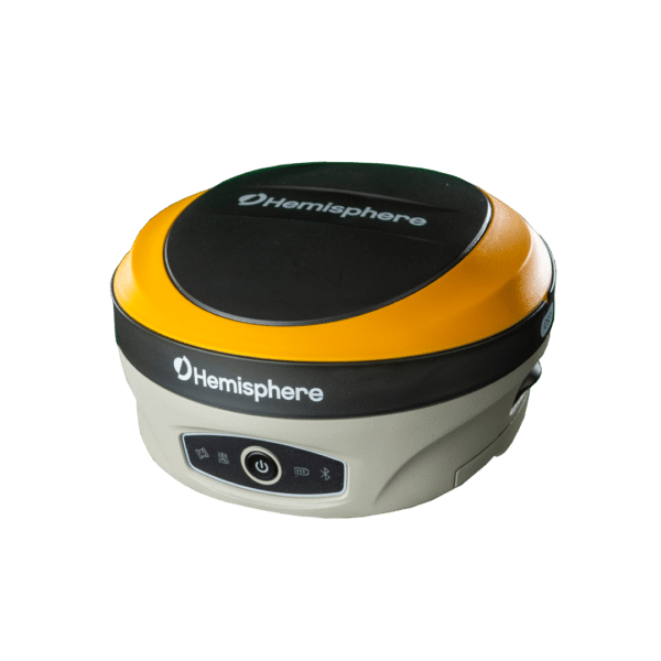
The Hemisphere S621 includes two batteries. Each of them provides six hours of operation. Battery life can be extended up to 16 hours for base units using Bench Mark’s external power kit. This allows your RTK GPS systems to operate continuously for long field days.
Hemisphere has been building GNSS technology for more than 30 years. After establishing itself in OEM, marine, and agriculture markets, Hemisphere expanded into surveying and construction with cutting-edge technology at aggressive pricing. This approach allows professionals to access top-tier RTK performance at a fraction of the cost.
Yes. Each GNSS receiver comes fully loaded, capable of tracking and measuring signals from all five satellite constellations, ensuring optimal coverage and accuracy.
The Hemisphere S321+ can achieve:
The Hemisphere S621 and the e-Survey E600H come with two hot swappable batteries, each with six hours of battery life. This battery life can be extended through the use of Bench Mark’s external power kit, which provides 16 hours of base operation; this means that one unit can go up to 28 hours to keep you going in the field.
All receivers come with built-in 1 or 2-watt radios, providing typical ranges of 5 to 6 km in ideal conditions. For greater distances, Bench Mark offers solutions like base booster radios (e.g., Harxon HX-DU8608D) or network options such as StormCaster to extend your RTK GPS system range.
An RTK base station is a fixed receiver that transmits correction data to a rover, improving positioning accuracy to the centimeter level. A reliable base station ensures stable, repeatable measurements and consistent survey precision, even across long distances.
For basic positioning, a GPS receiver may be sufficient, but most surveyors choose a GNSS receiver because it delivers higher reliability and accuracy by tracking multiple satellite systems. GNSS receivers maintain better performance near buildings, trees, and other obstructions, making them more versatile for professional surveying.
GNSS RTK uses real-time correction data with multi-constellation satellite tracking to deliver centimeter-level positioning accuracy for professional surveying, construction layout, and mapping workflows.
Choosing the right GNSS receiver depends on your accuracy requirements, project environment, and workflow. For high-precision tasks like construction layout and boundary surveys, an RTK-capable GNSS receiver is the best choice. For GIS mapping and asset collection, sub-meter or decimeter GNSS receivers may be sufficient. You should also consider battery life, radio and network connectivity, software compatibility, and field durability before making a purchase.
Trimble RTK systems are known for reliability and strong field performance, but many surveyors compare them with alternative GNSS RTK solutions based on workflow, compatibility, and overall value. Choosing the right RTK system depends on accuracy requirements, site conditions, and budget.
Do More With Bench Mark
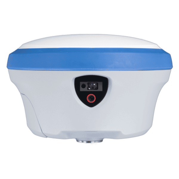
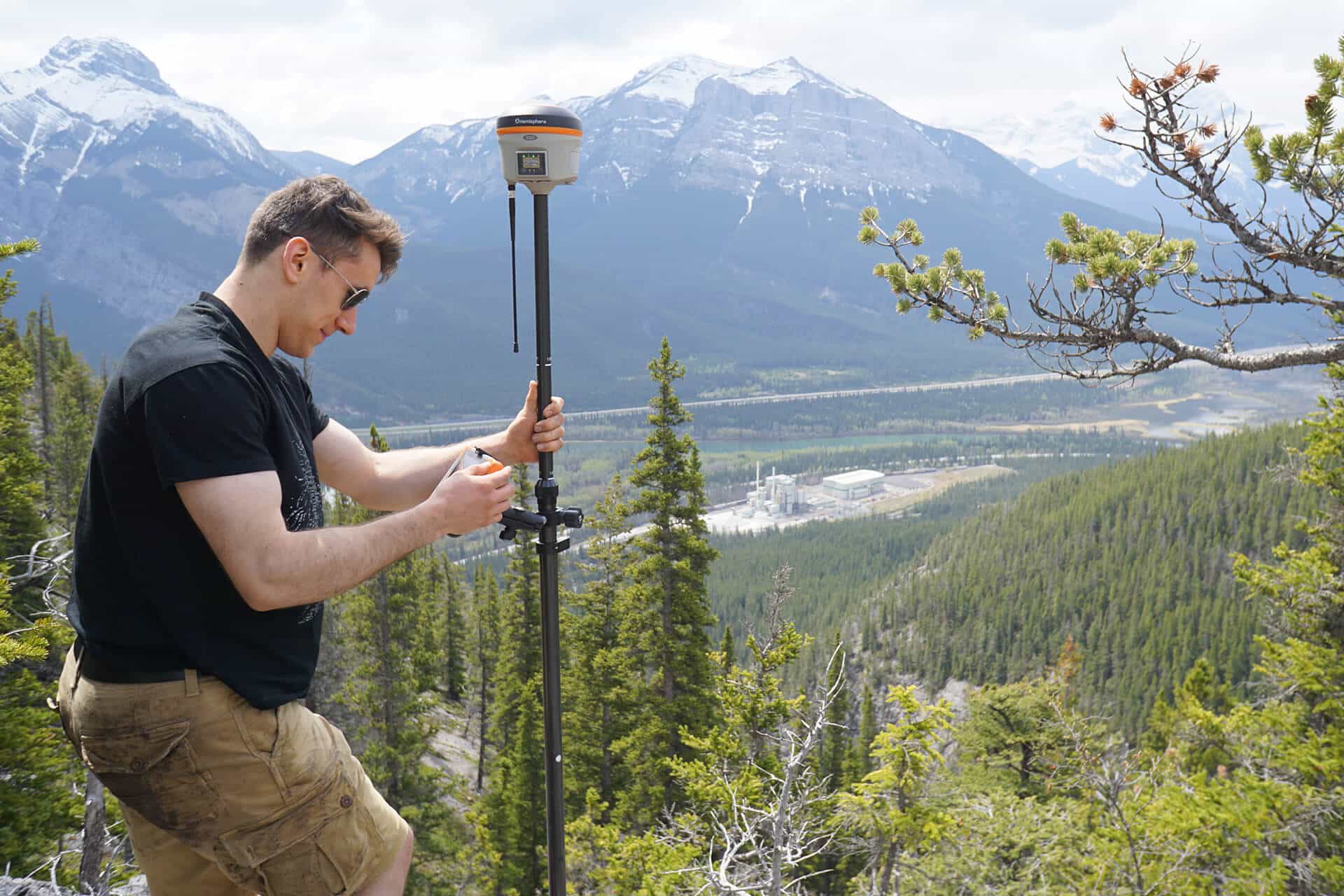
Our RTK GNSS receivers endure real-world conditions. They feature IP67-rated protection and rugged magnesium housings that withstand two-meter pole drops. The Hemisphere S631 offers advanced connectivity with Pacific Crest, Satel, and Trimble radio protocols, plus cellular data integration for seamless RTK network access.
These next-generation RTK GPS and RTK GNSS systems deliver fast, consistent performance, are user-friendly, durable, and packed with advanced field-ready features. Supported constellations include GPS, GLONASS, Beidou, Galileo, QZSS, IRNSS, and Atlas L-Band. Our GNSS receivers are customizable for specialty uses like hydrographic and echo sounding.
With proven expertise and a comprehensive product range, Bench Mark offers accurate and dependable RTK GNSS surveying solutions.
Reliable & Affordable Systems
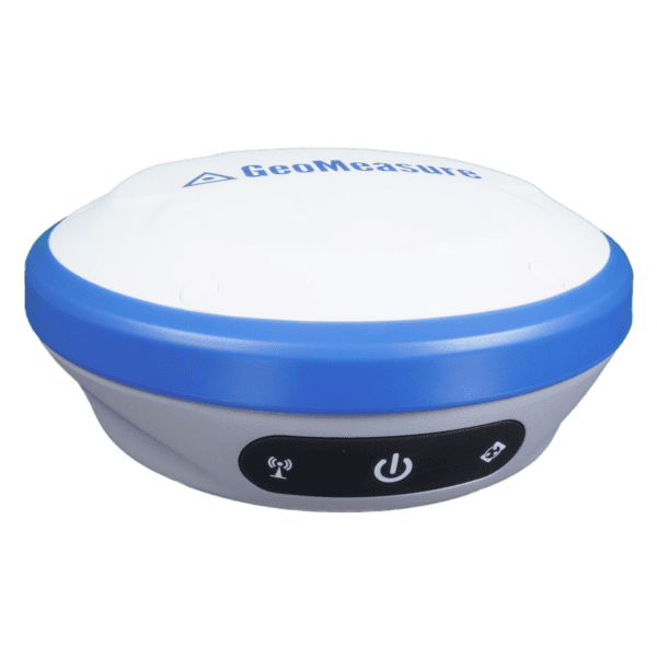
Serving over 1,300 clients across North America, Bench Mark has earned a reputation as Canada’s leading supplier of GNSS equipment. We offer top brands, including Hemisphere GNSS, CHC Navigation, and SatLab GNSS, while also supporting surveyors who work with Trimble RTK systems.
Our commitment doesn’t end at the sale. We provide ongoing technical support, personalized service, and the best pricing in Canada. If you need a Sub-Meter GPS unit, smart antenna, or a complete RTK GPS system, our specialists at Bench Mark can become your trusted partner in surveying technology.
